|
|
Alternator Testing
Alternator Repair
Tools Needed: Large & small blade screwdriver, a long 8mm Allen wrench, 17mm, 10mm & 13mm wrench, 3/8th's ratchet extension, Needle nose pliers, Needle nose Vise Grip pliers, 4" 3 jaw puller, 13mm & 19mm socket, ratchet wrench, seal driver, cheater bar, tommy bar, hammer and block of wood.
A. Russian 35A Unit (Oil Seal Replacement)
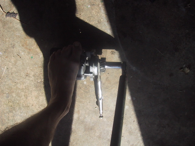
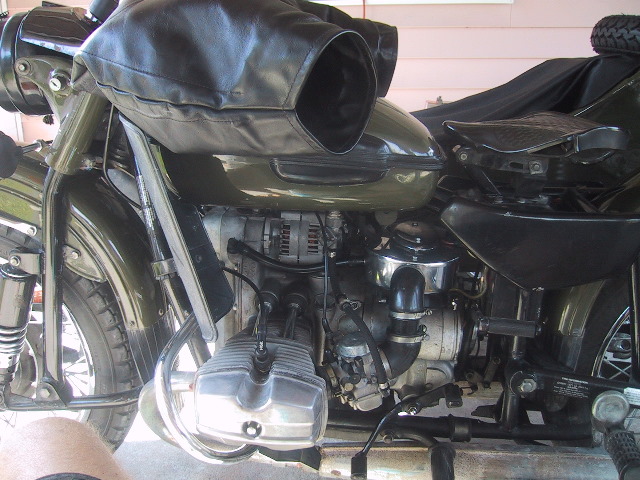 Left side view of bike showing alternator just under gas tank. |
 Begin the removal process by turning off the battery master switch (if installed) or disconnecting the battery. If you don't, you may end up welding a wrench to the bike! |
 Remove the side cover if installed...most just pull off. |
 Now, the air cleaner housing can be removed. |
 Pull the breather hose free... |
 ...of the housing. |
 Use a screwdriver to loosen the upper and... |
 ...lower branch tubing clamps... |
 ...and remove both the left and right tube assemblies. |
 On the right side of the housing, use a 13mm wrench/socket to remove the nut/washer holding the clutch cable bracket. Not the nut on the clutch adjustment screw...but the nut farther back securing both to the engine case. |
 Next, remove the top bolt on the starter which secures the left side of the air cleaner housing bracket. |
 Use the 8mm Allen wrench for this. I like the type with the ball end as they are easier to use. |
 Depress the kick start lever so it is out of the way. Hold it down with your foot or use a bungee cord. |
 If you have trouble breaking the starter bolt free, use a ratchet extension as a cheater bar. |
 With the two fasteners removed, the filter housing can now be eased out the left side. This is a good time to clean the air filter. |
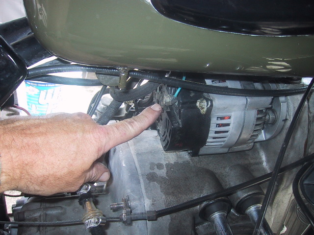
 The alternator now has enough clearance to be removed. |
 Before removing the alternator, mark the engine case and alt. housing so the original position can be maintained upon reassembly. I use a indelible ink pen. |
 Pull the male spade... |
 ...out of the back of the alternator. |
 Use a 10mm wrench to remove the nut... |
 ...holding the wires on the post. |
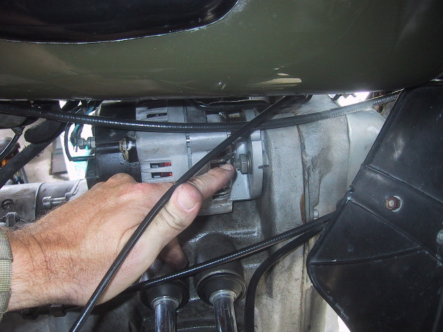 Remove the right... |
 ...and left alternator mounting nuts using a 17mm wrench. |
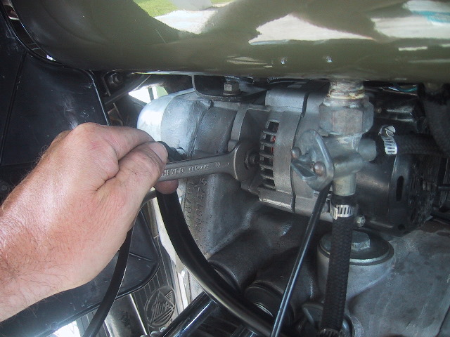
 The alternator can now be eased off its mounting studs. Use care not to tear the paper gasket underneath. If damaged you can make a new one from a brown paper bag. Use some silicone grease on both sides of the gasket to prevent it from sticking next time. |
 The alternator can now be easily slipped out.... |
 ...the right side between the bike and sidecar. |
 Just a couple views... |
 ...backside... |
 ...front side. |
 These are 4 bolts that need to be removed to split the alternator. I'll do a further tear down later in another section. For right now I'm just going to change out the oil seal which is leaking. A very common problem. |
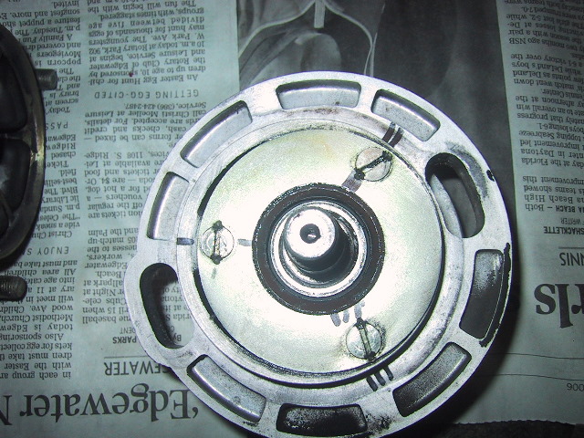
 You can just see the seal under the gear. The oil keeper spring is visible through the fuzziness. |
 To remove the seal the gear must come off first. Start by removing the cotter pin... |
 ...use the needle nose pliers to straighten the pin arms... |
 ...and pull it free. |
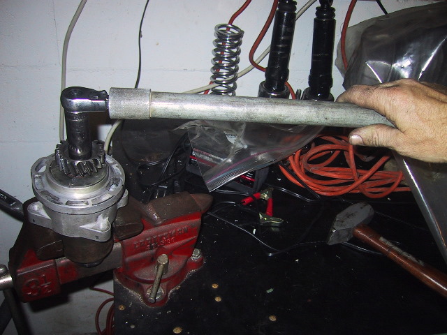
 Clamp the needle nose Vise Grips around the shaft of the gear, use the 19mm socket, ratchet and breaker on the bolt. Stand on the alternator body and turn the nut off. |
 Easy smeezy. |
 Attach a 3 arm puller to the gear. You will need a lead screw shaft protector (seen between the gear and screw) for the screw tip as the alternator gear shaft is not center drilled. |
 Hold the puller and turn the lead screw using the 13mm socket and ratchet. |
 The gear should come off smoothly will very little effort. If not, something is wrong or you are not using the right size puller. Watch for the gear key, it usually stays on the shaft. |
 Use a long thin blade screwdriver to pop the seal free. Notice it is installed face down. Be careful to not gouge the alternator seal housing with whatever you use to remove the seal. |
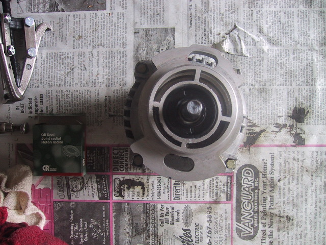
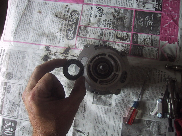 This seal is a standard 20X40X10mm seal available anywhere. |
 Get a good aftermarket brand seal. It is more common to find a 20X40X7 seal. |
 The 7mm deep seal will work just fine. Just seat it so it is at the same depth as the original. This means, do not seat it all the way down. |
 I put a little silicone grease on the inner lip of the seal. My bearing supply guy says this makes it wear in better and last longer. |
 Use an appropriate size driver to set the seal. Here I used a 1 & 1/8th's socket. A deep socket would have work better due to the base hitting the key which I left on the shaft. |
 Gently tap around the base of the socket to evenly seat the seal. Remember! If using the 7mm thick seal instead of the original 10mm thick seal; seat the seal to the same depth which is the top of the bevel in the race/housing. |
 Install the gear by using a block of wood... |
 ...to tap around the face of the gear... |
 ...so it is driven evenly onto the shaft until it is fully seated. |
 Use a new beefy cotter pin, not some tiny POS. If the cotter pin comes off; the gear will come loose and take out your timing gears. Tap the new cotter pin in using a tommy bar and hammer. |
 Bend the cotter pin arms with a pair of needle nose pliers and tap the arms down tight against the nut with tommy bar and hammer. |
The alternator is now
ready to be reinstalled in the reverse order of removal. If you didn't mark the position before removal or you want to adjust the gear lash by "ear"...the following is how it is done.
|
1. Install the alternator and rotate it CW to the stop (as seen from the rear), then rotate it CCW .12 to .15 inches/ 3 to 4 mm (measured at the outer diameter of the alternator frame). | 2. Secure the alternator in this position. Start the engine and listen to the alternator gear mesh. Stop the engine, rotate the alternator slightly, secure it, and start engine again. With incremental adjustments of the alternator position, the gear noise may be minimized which will signal the correct position. | If you have the engine out of the frame and the front cover off; use a dial indicator and stand to measure the gear last to .002 to .004 in at least 4 different positions and then secure alternator and recheck lash. |
B. Nippon Denso Unit (Adapter Disassembly)
 To separate the adapter from the Denso, remove the four 6mm nuts securing the adapter to the Denso alternator. |
 A back view of the alternator showing the propeller vanes which... |
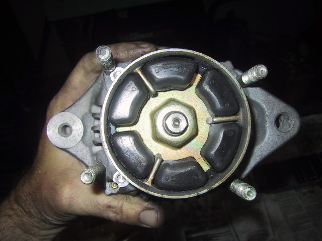 ...engage the rubber shock cushions. |
 A front view of the adapter showing castellated nut minus cotter pin which is meant to secure nut from backing off. |
 To remove the castellated nut and alternator drive gear, I placed a Ford 4X4 hub removal tool in a vise... |
 ...and placed the adapter on top so as to lock the propeller vanes from turning. |
 Remove cotter pin from nut...what was left of mine was laying at the bottom of the timing gear tower. |
 I used a socket, 3/8" ratchet and cheater bar to break the retaining nut loose. |
 A small 3 arm puller was employed to remove the alternator drive gear. |
 Now you can see the bearing cover plate. |
 The 3 screws used to secure the bearing plate are staked. |
 I used my clutch screw removal tool to take out these screws. |
 The propeller shaft can now be pressed or tapped out with a hammer. |
 The two #6004 RS bearings in this adapter had spun and galled to the shaft. They had run dry and self destructed. The seal is a fractional mm seal only available through a URAL dealer. The seal is a # 62-06162-10 and it is 25X36.5X8 mm. Around the 2005 year model IMWA began phasing out the fractional seals on the bike and changed the above seal to a standard 25X35X7. |
It took a couple licks of a torch and a 20 ton press to get the propeller shaft free due to being galled on the shaft. |
|
|