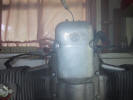
Make sure the key and ignition are turned off.
Begin by removing the front timing cover. This
cover will either be plastic or metal and have one fastener on each
side. OEM fasteners are slotted flat head screws. I recommend that
you change the following screws to cap head machine screws. |
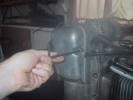
In my case, I am using a 5 mm Allen wrench to remove
my fasteners. Use the appropriate tool for your fasteners. |
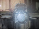
Remove the timing cover and place the screws inside
the cover to prevent loss.
With a TYPE IV ignition you will be now looking at
the ignition microprocessor (aka, the silver hockey puck) and coil
mounted above. |
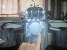
The microprocessor... |
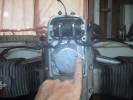
...the red LED... |
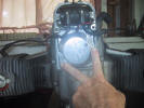
...and the 2 set screws which hold the microprocessor
to the back plate. |
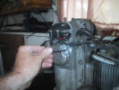
Remove the 2 set screws. The OEM screws are slotted.
I am using a 4 mm Allen wrench to remove my after market machine
screws. Place the screws in the timing cover to prevent loss. |
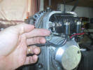
Coming out of the top of the microprocessor is 1
black wire and 1 red wire... |
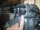
...these wires attach to one of the two coil spades.
It does not matter top or bottom, just that one wire goes to one
side and the other wired to the opposite side. |
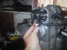
Remove the red and black wires from the coil.
Caution as the microprocessor
is now free to fall off the cam! |
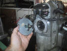
The microprocessor easily slides off the cam and back
plate. You can see the Hall's pick-up on the back of the
microprocessor at 3 o'clock. Place the microprocessor inside the
timing cover to prevent damage. |
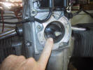
This is what we are after, the Interrupter... |
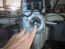
This is the 10 mm bolt and washer that holds the
Interrupter onto the cam...
|
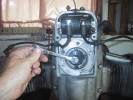
...use a 10 mm wrench to loosen and remove the bolt. |
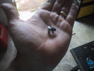
Bolt and washer removed. Place these with the other
fasteners in the timing cover. |
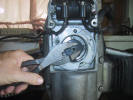
You may or may not need to use a pair of pliers to
gently twist the Interrupter free of its seat to the cam. |
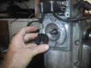
Slide the Interrupter off the cam. |
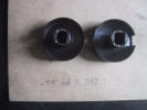
On the left is a early manufactured two-piece swaged
joint Interrupter. On the right is the newer one-piece machined
Interrupter. The two are easy to distinguish as the two-piece has a
shoulder where it meets the round skirt... |
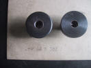
...and a definite swaged seam on the back. The
one-piece Interrupter is devoid of these.
If you have the early two-piece replace it at once
with the one-piece. The two-piece will
fail causing timing issues from
a slight miss to not running and everything in between
depending on how much the swage joint is slipping back and forth.
|
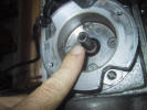
Notice the two "flats" on each side of the cam... |
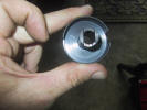
Those flats are where the Interrupter grabs onto the
cam. |
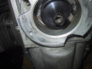
Slide and spin the new Interrupter onto the cam until
it seat fully and can no longer turn. Replace the retaining bolt and
washer and tighten it down with the 10mm wrench. Replace the
microprocessor and hook up the 2 wires to the coil and perform the
timing procedure as in section "A". |
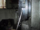
This is a side view of the microprocessor on the base
plate. A the end of the pointer you can see the lubber line on the
microprocessor body. To the immediate right you can see the 7 hash
marks on the base plate. When the timing is set correctly, the
lubber line should be very close to the middle hash mark (4th
counting from either side). If it is not, something is wrong with
the Interrupter. Recheck your work. |
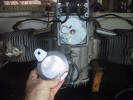
The only difference with the TYPE V ignition is the
microprocessor which I am holding is mounted externally on the motorcycle frame... |
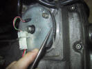
...the Hall's pick-up is mounted to a separate plate
that is held to the base plate
with the 2 set screws. The removal and setting of the timing are exactly the same
as with the TYPE IV ignition.
Usually, the Russians mark the plate with a lubber
line as shown next to the pointer. If yours does not have one, the
round hole in the plate should be centered next to the 4th hash mark
on the base plate. Once you have set the timing, make you own
reference mark. You can use this to set the timing without going
through the entire procedure as in section "A". |
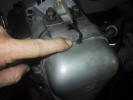
When reinstalling the timing cover, do not pinch the
12v power wire in between the cover and engine block. This will
cause a short and the ignition will not function until the wire is
repaired. |
Note:
Occasionally after removing and installing the Interrupter, within a
short timing of running the engine the bolt can loosen or the
Interrupter will move on the cam slightly causing a timing misfire.
Simply go back and remove and reseat the Interrupter and retighten
the 10mm bolt. From then on you should be good to go. |
|
|
|