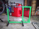
You will need something to hold the crank. Here I
have the crank on my Rod Neff balancer. You can chuck it up in a
lathe or think up some other simple way to suspend the crank. |
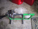
A view from above. The left arm of the balancer is
adjustable in the vertical and the right arm is adjustable in the
horizontal. Both bearing heads pivot so walking of whatever you are
balancing can be eliminated. |
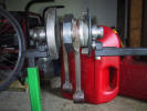
Close up of crank on balancer. |
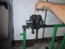
Use a set of feeler gages to measure the axial play
between the rod big ends and crank cheeks |

The axial play should be between .008" and .013"
(0.20/0.34 mm). |
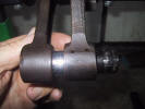
Check the trueness of the rod arms by slipping a 15mm
deep socket between the rod small ends. The socket should slip
through without binding. If it binds, at least one rod arm is bent. |
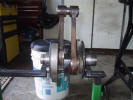
How's this for balance? |

Here is an example of an obviously bent rod arm. The
socket will not go through the small ends. A crank with a bent arm
is not repairable and must be replaced. |

Using the 15 mm socket, set up a dial indicator as
shown and measure the turning of the crank pin. Measure the crank in
two spots. If the tolerance exceeds .020" (0.50 mm) between the two
measurements, the crank will need to be replaced. |

Next, check for radial play of the connecting rod. |

To do this properly the crank should be chucked
up at the ends so it does not move. Once secure, set the dial
indicator up on the big end of the crank arm and while grasping the
small end push toward the dial indicator. If the radial play of each
arm exceeds .004" (0.10 mm) the crank should be replaced.
|
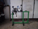
To measure the run-out of the crank, set up a dial
indicator on each of the main journals... |

...turn the crank and watch the deviation of the
needles. The needles should deviate in the same direction; both
positive or both negative. The maximum permissible run out is .020"
(0.05 mm). If the dial needles go opposite of each other the crank
needs to be replaced. |
|
|