|
|
|
|
Final Drive Repair With 2wd
Note: This DOES NOT cover the "Sportsman" final drive (pre-2000)
Tools Needed: 13mm, 17mm wrench, axle, URAL pin spanner, magnetic pick-up, long shank thin blade screw driver, hammer, tommy bar, 41mm (1&5/8") socket, 19mm deep socket, 15/16" socket, 12mm socket, ratchet, 4" extension or longer, 3/4" tip wood chisel, wood blocks, empty oil bottle, needle nose pliers, LocTite, grease, lip stick, vise and a hammer.
7.7(a): Pinion Gear Rebuild
 The pinion gear on the right is the original pinion gear which I was going to re-use as it was within spec...but notice that the shoulder (just ahead of teeth) for the inner needle bearing race is worn away. The new pinion is on the left. |
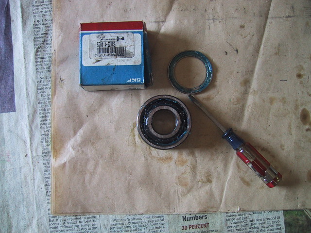
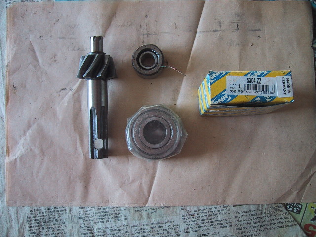 The new pinion gear, needle bearing and #205 bearing ready to be pressed on. |
 I pulled the seal on one side of the bearing only. The sealed side will be mounted outward toward the drive shaft as an additional seal. |
 The outer needle bearing race has a beveled side which should be mounted facing toward the tip of the pinion gear. |
 Place the inner race on something firm like a concrete floor and carefully tap it home making sure you do not cock the race on the pinion shaft. |
 View from above of inner race seated. |
 Now the #205 bearing can be pressed on. |
 Start in on the pinion shaft in the same manner as the needle bearing inner race. Note the "open" end of the bearing is facing the teeth... |
 ...while the sealed side is facing where the drive shaft will slide on later. |
 Finish tapping the pinion gear through the bearing by placing the bearing over the open jaws of a vise. The vise jaws should support the wall of the inner race of the bearing. Alternatively, if you have use of an Arbor press; both bearings can be pressed on with it. |
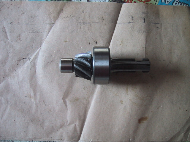 Three views of the assembled pinion gear, side... |
 ...top... |
 ...bottom. |
 Grease the inside of the needle bearing outer race and place the 28 needle bearings inside... |
 ...place the outer race with needle bearings on the end of the pinion gear and store in a plastic bag until time to install the unit in the final drive case. |
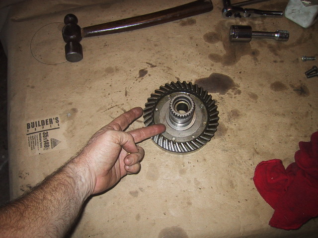
7.7(b): Driven Gear Hub/Ring Gear Rebuild
 On the right is the oil driven gear hub with worn splines. The splines are what mate to the wheel hub splines. A new unit is on the left. |
 Worn splines... |
 ...new splines. |
 All the new parts needed for assembly. Driven gear hub, half moon lock washers, ring gear, shims, spacer, 22X40X10 seal, #1000822 (110X140X16)bearing and 8 M12 X 1.25 bolts. |
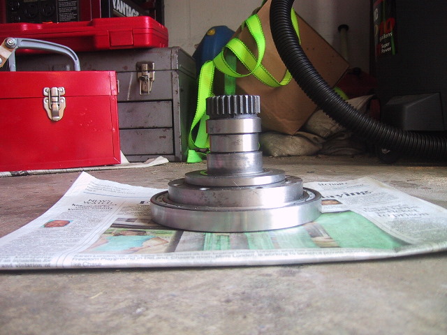 Place the #1000822 bearing on a hard surface and set the driven gear hub atop it. |
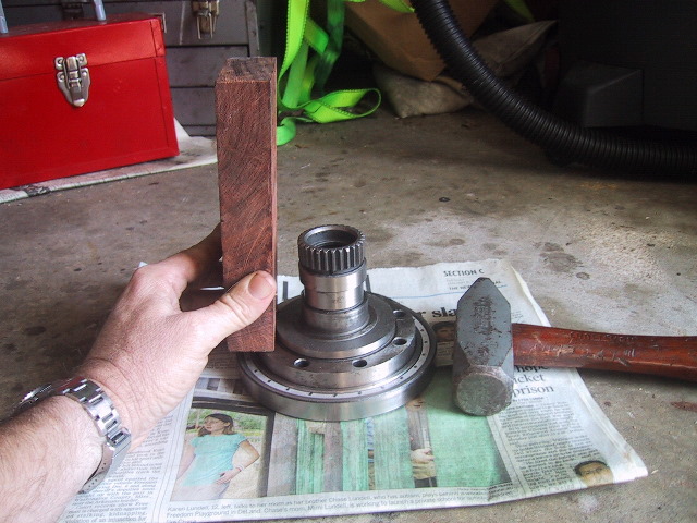 Use a hard block of wood and hammer to gently tap in a cross pattern 9 o'clock... |
 ...3 o'clock... |
 ...12 o'clock... |
 ...6 o'clock. Whilst doing this keep the hub as level as possible. |
 Seat the hub level to the shoulder of the bearing as the ring gear must sit on top the two pieces. |
 Side view of driven gear hub seated in bearing. |
 Take the ring gear and place it on top of the hub assembly. Take care in aligning the bolt holes. A couple of light raps on the floor should be enough to seat it. |
 If needed, a couple light blows with a tommy bar and hammer will finish setting the ring gear. |
 When turned over, the driven gear hub should be slightly recessed into the bearing. This is so the half moon washers and bolts will not come into contact with the shift coupling gear in the outer case. |
 The half moon lock washers fit like so... |
 It is easier to pre bend the ends of the washers in a vise. Bend them up approximately 45 degrees. |
 Bend the top side which is facing outward on the hub assembly. |
 Using a ratchet and 12mm socket, install the 8 bolts. |
 Use a wood chisel or similar tool and a hammer to bend the half moon washer tabs up on the bolt flats. |
 Use a tommy bar and hammer if needed to finish the job. Sorry about the camera leash... |
 On the left is the original spacer. You can see when compared to the new one on the right that the ends are worn away. Time to replace it. |
 Turn the hub assembly over and drop the spacer inside the axle channel. |
 Spacer is in and the 22X40X10 seal is ready to install. |
 The seal needs to press down to this lip inside the channel. |
 The seal goes in face down. You should be looking at the side of the seal with the tension spring. |
 It is very easy to damage the seal when seating one "upside down". I used a 15/16" socket with an extension going through the socket so the base of the socket was in contact with the seal. |
 Carefully align the seal in the hub channel. No cocking is permitted or you will damage the seal. Slowly tap the seal down, removing the socket and checking progress every few taps. |
 Once the seal is in place turn the driven gear hub over. All that is left is to install the bronze and steel spacers on the shaft. |
 The bronze spacer goes on first. There is only one thickness of this spacer. |
 The steel spacer goes on second (hence the two fingers). There are 4 thicknesses of this spacer; 1.1mm, .95mm, .8mm and .65mm. These in conjunction with the final case gaskets are used to set the gear lash between the ring and pinion gears. This will be discussed further in 7.9(i) below. |
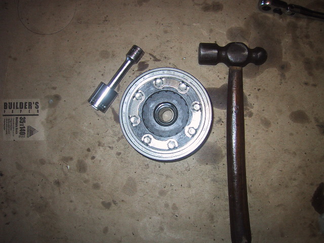
7.7(c): Splined Hub Rebuild
 Splined hub and #204 bearing awaiting installation. |
 Once again, I remove only one seal from the bearing. |
 Set the splined hub on the floor, set the bearing on top with the sealed side facing up... |
 Use a hammer and block of wood to tap the bearing in... |
 ...using a cross pattern. Use care not to cock the bearing while seating it. |
 The bearing must be seated onto a recessed shoulder in the splined hub. I used the back end of a 41mm (1&5/8") socket... |
 ...a hammer and block of wood...
|
 ...to press it down. Notice the sealed side of the bearing is facing out. This is another barrier to oil leaking out and dirt/water getting into the final drive. |
Assembly of the splined hub is now complete. |
7.7(d): Outer Case Rebuild
 All the parts ready to assembly; hammer, outer cover, 55X80X10 seal, 2wd detent screw, shift coupler, pins, shift yoke, lever shaft, cotter pin, C-clip, 25.1X12.3X7 seal, #7000111 (55X90X11) bearing, tommy bar and pliers. |
 Place the 55X80X10 seal face down in the outer housing. |
 Use the large end of the splined hub as a driver. Place the outer case on the floor or other hard surface... |
 ...use a block of wood atop the splined hub and hammer to lightly tap the seal down using a cross pattern. Stop every few strikes and check condition of seal. It is very easy to damage the seal when driving it on the backside on the seal. |
 Seal fully seated. |
 Next, place the #7000111 bearing in the outer housing... |
 ...using a tommy bar and hammer... |
 ...seat the bearing using a cross pattern of strikes. |
 Bearing fully seated atop seal. |
 New the 25.1X12.3X7 seal can be installed. |
 I used a 19mm socket... |
 ...and hammer to fit it flush to the case. |
 The splined hub can be fitted next. Place the hub on the floor and set the outer case over top the hub... |
 ...use a tommy bar and hammer to tap around the inner race of the #7000111 bearing to seat the outer case onto the splined hub. |
 Next the C-clip must be installed to hold the splined hub in the outer case. More easily said than done. |
 Slip the clip over the splines... |
 ...start one side over the shoulder of the splined shaft... |
 ...and while holding that side of the clip down use a large screw driver to pry the other end over the opposite shoulder while using your fingers to push the clip down until it snaps into its groove. The clip should move easily in its groove. |
 Next, slip the shift coupler guide pins into the shift yoke... |
 ...like so. |
 The blocks on the pins ride in the groove of the shift coupler gear. |
 Set the gear down and slide it onto the pins... |
 ...like this. |
 Slip the shift coupler over the splined hub with yoke to the right. |
 The 2wd shift lever shaft can now be inserted through the seal and yoke... |
 ...insert the shaft so there is approximately a 45 degree angle to the face of the case with the lever pulled fully aft (right). |
 I made a new cotter pin to secure the 2wd lever shaft to the shift yoke. |
 Insert the cotter pin into the hole... |
 ...and bend the long arm of the pin to secure it. Not a great picture, but if you look hard you can see the pin arm bent toward the camera. |
 Now the 2wd lever detent screw can be fitted and the outer case will be complete. |
 I use some thread compound to seal the threads, LocTite will work as well.
|
 Screw it down far enough so that when the engagement lever is aft, the upper part of the yoke forces the ball detent 3/4 the way up inside the screw. |
 Here is a picture of with the 2wd lever forward pushing the shift coupler gear up the splined hub teeth, the ball detent is at the upper 12 o'clock position. |
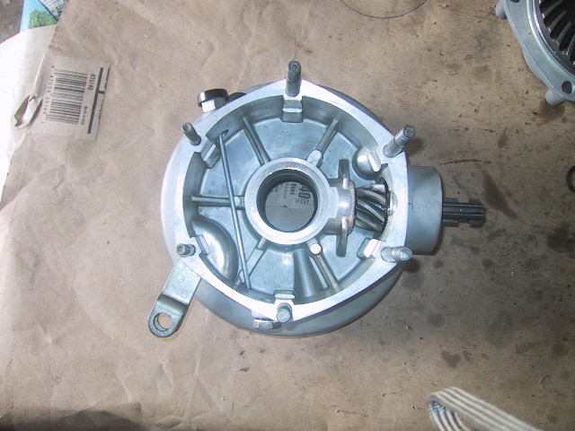
7.7(e): Final Drive Case Rebuild
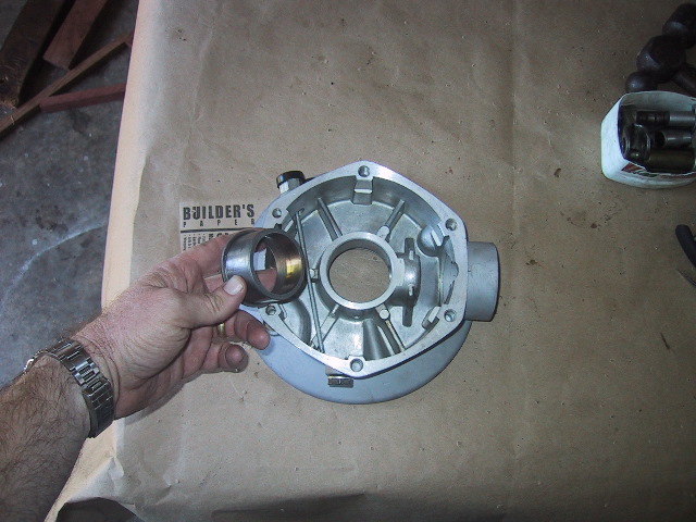 If removed, place the final drive case bushing in the final drive case... |
 ...and use a hard block of wood and hammer to tap the bushing into the case. |
 Bushing seated. |
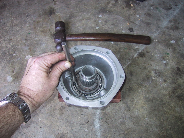
 Next, press the pinion gear needle bearing outer race into the housing where I'm pointing. |
 Set the final drive case on end supported by wood blocks and place the needle bearing outer race over its hole... |
 ...use a 19mm deep socket, extension and hammer... |
 ...to tap the outer race flush in the case. Go slow and do not cock the race in the hole. |
 If you are replacing the rear brake cam bushing... |
 ...push it squarely in the hole and use a hammer and piece of hard wood to drive it in... |
 ...only drive it down until it is even with the top of brake distance ring. |
 This bushing has a little more ways to go before flush with the distance ring. Alternatively, if you have access to an Arbor press... |
 ...you can press both brake cams in place. On the leading brake cam make sure you put the distance ring on first and put a brake shoe in place to get the proper press depth. |
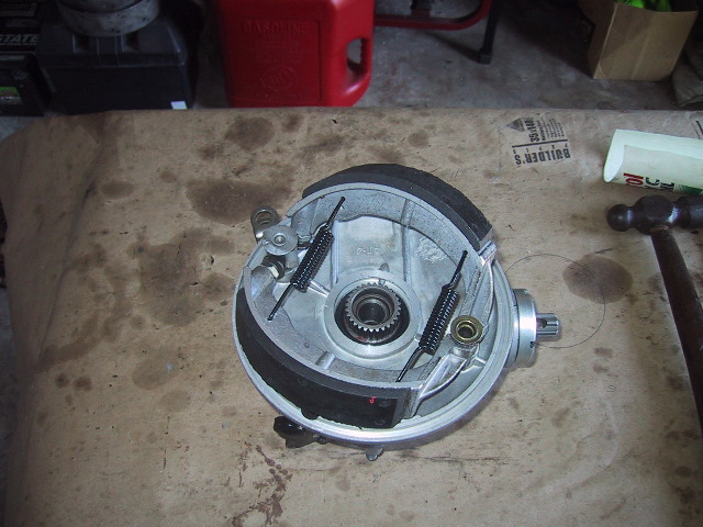
 Collect the rear brake components and put them on next. |
 Grease and place the distance ring over the rear brake cam bushing... |
 ...grease and insert the rear wheel brake cam into the bushing. |
 Set the rear wheel brake cam in so the tip of the shoe plate is aligned with the web I am pointing to on the final drive case. |
 While holding the rear wheel brake cam alignment; set the rear wheel brake lever onto the splines of the rear wheel brake cam. |
 Snap the brake shoes into place... |
 ...and slip the rear wheel brake lever onto the splines... |
 ...so that it is approximately 33 to 40 degrees back from the vertical. Book spec. is 33.5 degrees. |
 Secure the rear brake lever with the washer, lock washer and 13mm nut. |
 Use a 13mm wrench to snug the nut up. |
 All that is remaining is to put the final drive case studs in. I use blue LocTite on the threads. Note: The course (1.25mm) threads go into the housing, not the fine (1.00mm) thread side. |
 There are 2 long studs, 2 medium and 2 smaller studs. The longest go in the 2 and 4 o'clock positions, the medium in the 12 and 6 o'clock positions and the smallest in the 10 and 8 o'clock position of the case. |
 Double nut the studs and turn them in snuggly. You don't need to over torque them and strip the threads at this point. Hint: If you will need to set the lash on new gears, only put in the 2 forward (largest) studs. |
 Put the final drive bearing nut (3 o'clock position) on just so it does not get lost or damaged. Remember! The bearing nut is left hand thread!! |
Final drive case assembly is now complete. |
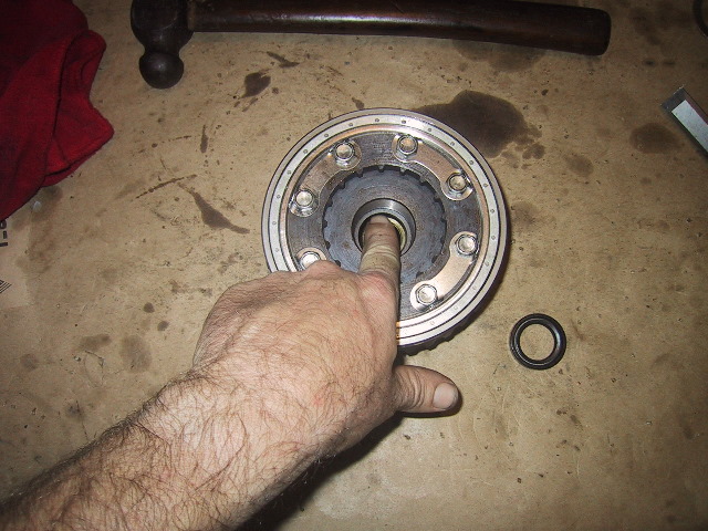
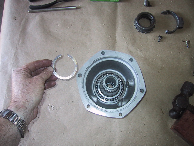
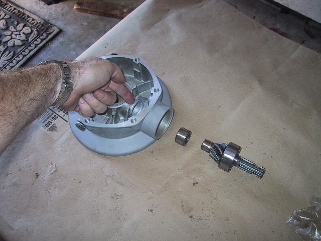
7.7(f): Installing Driven Hub in Outer Case
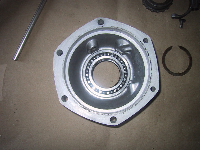
 On the left is the completed outer case, the right, the completed driven gear hub with #1000822 bearing mounted. |
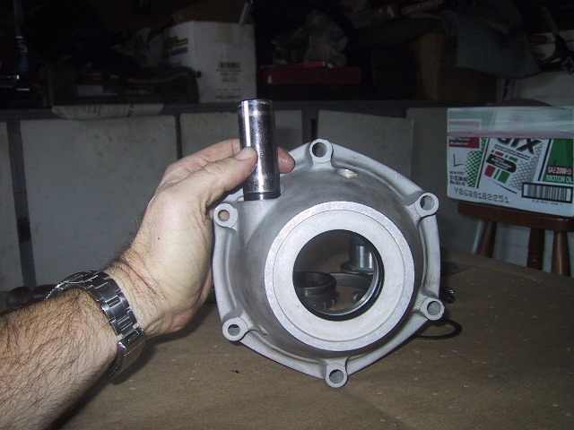
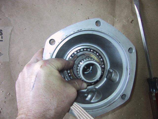
 DON'T DO THIS! The proper way is to insert the spacer bushing into the seal inside the driven gear hub. The bushing should have a bright ring from where the seal was riding. Use this as your guide for seating the bushing into the seal. |
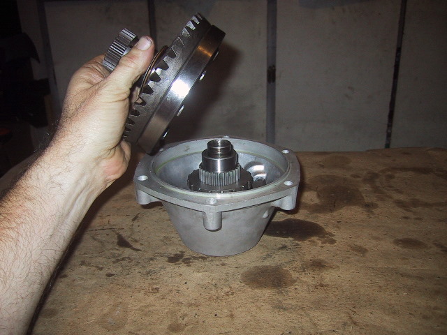 With the long bushing seated (it would be sticking out of the driven gear in this picture), place the driven gear hub atop the outer case. |
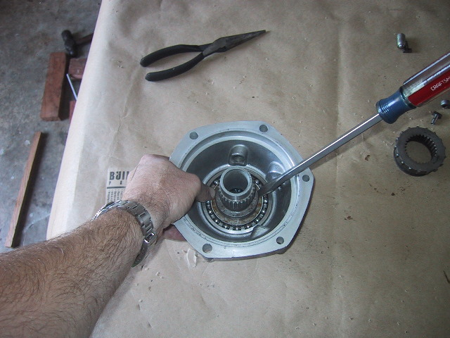
 My finger is pointing to the outer race of the #1000822 bearing. Make sure it is square to the mouth of the outer case... |
 ...and gently tap the driven gear hub into the outer case using a hard block of wood and a hammer. Check that the driven gear spins freely and is not bound up. |
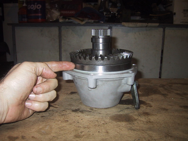
 If you detect some dragging or binding in the parts, insert an axle and give a few light taps with a hammer. Don't strike hard with the axle as shown above as this will separate the two halves again. |
 Try both sides and see if things don't loosen up. Again, don't strike hard, you can pinch the seal inside the driven gear hub between the short and tall spacer bushings. The way to prevent that is to seat the long spacer as described above. |
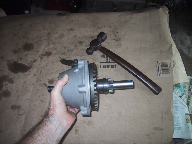
Set the completed outer case aside until ready to set the tooth contact and gear lash. |
7.7(g): Installing Pinion Gear into Final Drive Case
 The parts needed for pinion gear installation are along the bottom of the photo; final drive, 28 needle bearings (in pill bottle), completed pinion gear, shims and bearing nut with O-ring and seal installed. |
 Use some grease... |
 ...and with your finger, grease the inside of the outer race of the needle bearing in the final drive case. |
 Make sure you have all 28 needle bearings and place them on a clean surface... |
 ...put a little grease on the end of a finger... |
 ...press your finger onto the loose needle bearings... |
 ...and pick a few up and wipe them off into the grease in the needle bearing outer race. |
 Take your time and make sure the needle bearings are lined up properly in the outer race, taking care that none have been pushed to the bottom of the hole. |
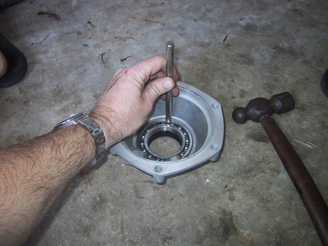
 Next, carefully insert the completed pinion gear into the final drive case. |
 Turn the case on end and press moderately on the end of the pinion gear to seat the tip of the pinion into the needle bearing and seat the #205 bearing. You may need a light tap with a hammer. |
 Lay the final drive case back on its side... |
 ...and screw the bearing nut lightly into the case. Remember, the nut is a left hand thread so CCW to tighten. |
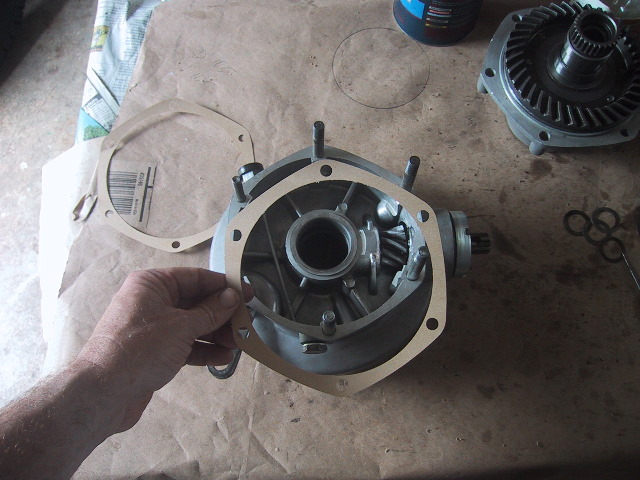 If you like, you can put one paper gasket in place at this time. You should have at least 4 of the gaskets as they are used to set the gear lash. |
 Sometimes the holes for the studs are small and the gasket can be damage when applying or removing it. I use a wad punch to open the holes up slightly. |
 Final drive case is now ready to set the tooth contact and gear lash with the outer case. |
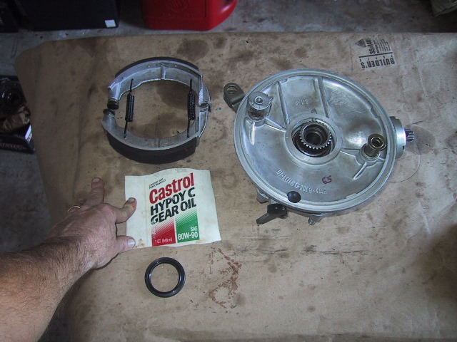
7.7(h): Checking Gear Tooth Contact
 To check the tooth contact, you will need some gear paste. Lipstick will work just fine. |
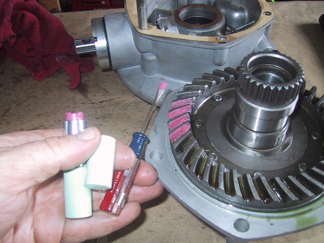 Use a small flat blade screw driver or similar tool to apply the paste/lipstick to 3 or 4 of the ring gear teeth. Line these teeth up between the stud holes in the case so that when mated; the pasted teeth are over the pinion gear. |
 The pinion gear is shown with the 3 different size shims. The shim sizes are .08mm, .18mm and .40mm. An extra one snuck into the picture. These shims are used to move the pinion in or out of the case as needed. |
 Seat the outer case onto the final drive case with the pasted teeth over the pinion gear. With one hand pressing down of the outer case... |
 ...roll the pinion gear back and forth several times to get the paste on the pinion teeth. Now remove the outer cover and examine the pinion teeth. |
 The paste should be mainly in the middle of the pinion gear tooth. Approximately 2mm to 4mm of the end of each tooth should be free of paste. |
 Rarely, the tooth contact is too far aft in which case you would need to place spacers between the pinion teeth and inner needle bearing race to push the pinion back. This means disassembling the pinion gear. |
 If the paste is mainly forward on the teeth, you will need to stack shims behind the #205 bearing so when the driveshaft is bolted up it pushes the pinion forward. The above picture... |
 ...and the following two are showing the 3 teeth on the pinion that the paste was transferred to. |
 It is difficult to see, but there is a clean 2mm border on each end of the teeth. Bulk of the paste is in the middle of the each tooth. When satisfied, proceed with setting the gear lash. |
7.7(i): Setting Ring & Pinion Gear Lash
 Here is the completed outer case, the bronze spacer and the 4 different thickness steel spacers used for setting the gear lash. |
 The spacers are 1.1mm, .95mm, .8mm and .65mm thick. If you cannot visually tell them apart or do not have a micrometer; use a kitchen scale with grams setting to separate them. |
 Start with the thinnest steel spacer... |
 ...and set it on the hub... |
 ...then put the bronze spacer on top of the steel... |
 ...there is only one size bronze spacer. Hint: Put a dab of grease under the steel and bronze spacer to prevent them from falling off when you invert the cover during assembly. |
Start with one paper gasket. Use more to fine tune the lash if needed. |
 Place the outer case on top of the final drive. Take care the spacers do not fall as they will prevent the two halves from mating completely. |
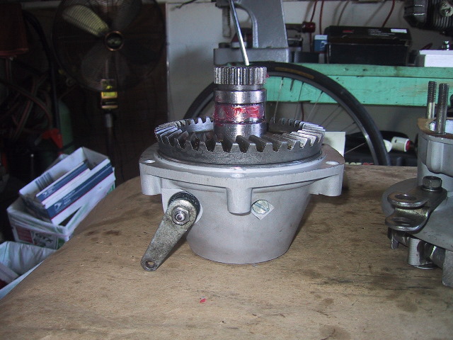
 Turn the pinion a bit to make sure the outer cover is fully dropped into place. |
 Press or tap firmly with a hand to seat the two parts fully. |
 Set up a dial indicator on the splines of the pinion gear. Make sure the pinion gear is resting against a ring tooth so there is no slop in the reading. |
 Carefully rotate the pinion until it hits the next ring gear tooth and note the reading on the dial indicator. Look for a lash setting between .003" and .006"/.07 to .16mm. |
 A view of one of the many ways to place the dial indicator on the pinion. |
 The easiest way to separate the two halves while switching spacers and gaskets is to turn it over and using both hands as above, press with thumbs to push off the outer casing. |
Switch steel spacers and add paper gaskets as necessary to achieve gear lash within the specified limits. When you are satisfied, you can proceed with the final assembly of the final drive. |
7.7(j): Final Assembly of Outer Case & Final Drive Case
|
It is time to install the 45 3mm X 15mm 8A5 needle bearings in the driven gear hub groove. |
 Put some grease on a finger... |
 ...and lube the groove slightly to hold the bearings. |
 Place the bearings on something clean and pick them up with a little grease on your finger. |
 Wipe them into the groove. |
 Take a moment to make sure the needle bearings are all seated correctly and none have fallen off. |
Have the completed final drive case ready to accept the outer case. |
Slip the outer case onto the studs... |
...rotate the pinion slightly to assure the teeth have meshed... |
...and tap the outer case to seat it into the final drive case. |
 Retrieve the two 13mm washers and nuts... |
 ...place them... |
 ...on the two smallest studs... |
 ...and using a 13mm wrench, tighten them down snuggly. For the anal folks out there; torque to 11 ft/lbs or 13.7 to 17.6 Nm. |
 Now the final drive case seal can be installed. |
 Turn the final drive over and remove the brakes shoes if installed. Cut an approximately 6" X 6" piece of plastic bottle to use as a mandrel. |
 Roll it up to form a cone... |
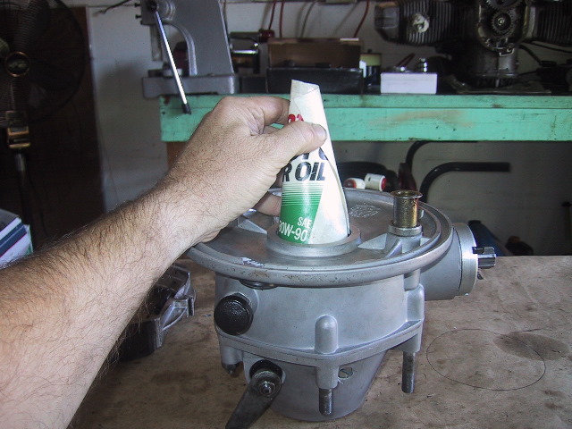 ...and slip it over the driven gear hub splines... |
 Slide the 45X59X7 final drive collar seal over the mandrel. |
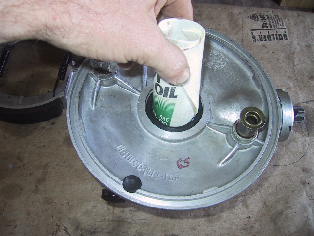 Using your fingers, push the seal down into the final drive past the splines. You should be able to seat it well past the weep hole in the case. |
 Carefully remove the plastic mandrel. |
 Use a thin piece of wood or something similar along with a hammer to tap the seal the rest of the way home. |
 Pop the brake shoes... |
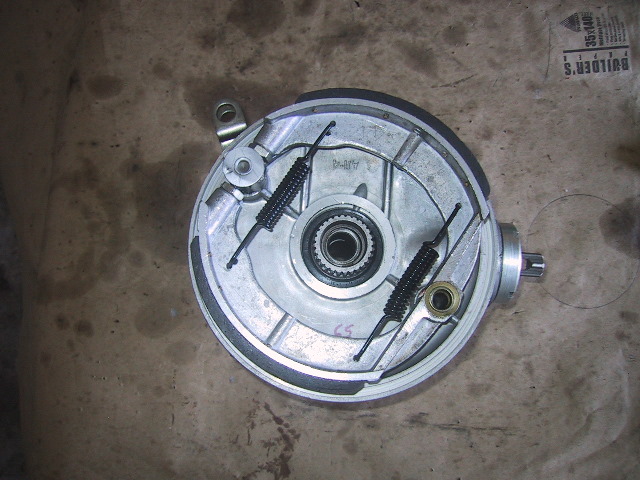 ...back on... |
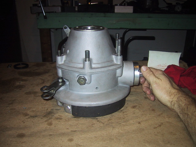
 ...flip the completed final drive right side up and all that is left to do is attach the driveshaft. |
7.7(k): Installing Drive Shaft
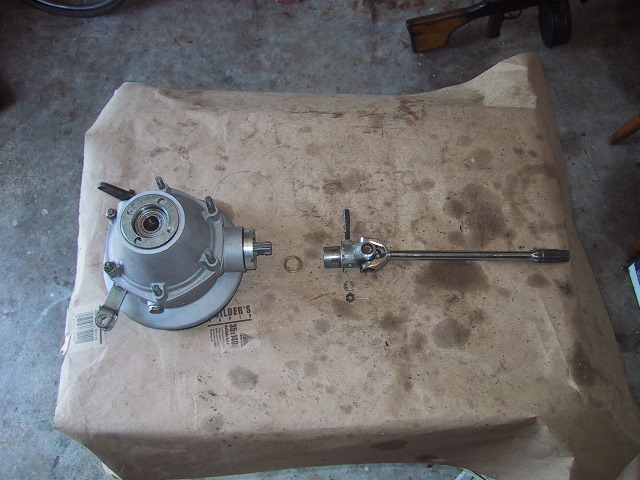 The completed final drive is on the left, then the pinion shim, the wedge bolt is above the driveshaft U-joint and the driveshaft. Below the U-joint is the washer, castellated nut and cotter pin for the wedge bolt. |
 Slip the pinion shim or shims as the case may be; on the pinion gear splines. |
 Rotate the wedge bolt holes in the pinion so the holes are at 12 and 6 o'clock. If you look closely, the holes are slightly off from each other. Have the forward most hole at the 12 o'clock position... |
 ...so the slant of the holes are angled like so... |
 ...another view demonstrating the same. |
 The wedge pin has a rounded backside... |
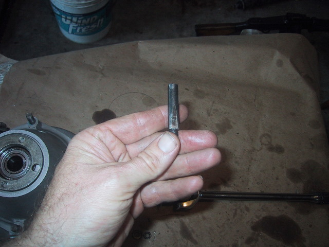 ...and a front side with a tapered "flat" at the bottom just above my thumb. |
 The side with the "flat" must face the driveshaft U-joint. |
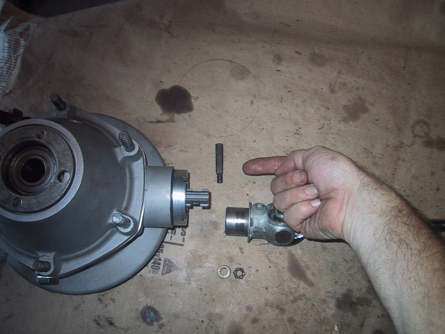
 Position the driveshaft so the raised shoulder of the wedge bolt hole is at 12 o'clock and slide the driveshaft onto the pinion splines. |
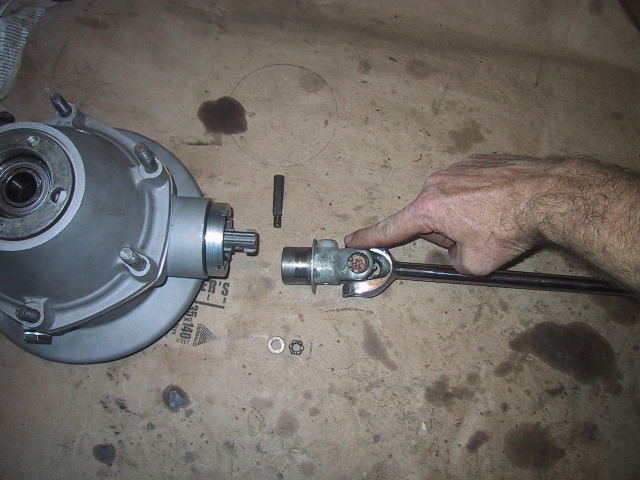
 Use a hammer to gently tap the wedge bolt (flat facing forward) into the hole. You should not need to "pound" the bolt through. If so, something is amiss and you should stop and investigate. The hole for the wedge bolt cotter pin is clearly visible at the threaded end of the bolt. |
 Place the washer and castellated nut on the wedge bolt and use a 13mm socket in the confined space to tighten the nut enough to get the... |
 ...cotter pin through the slots in the nut. |
 Bend the long arm of the cotter pin to secure it in place. |
 The top of the wedge bolt should not go below the shoulder in the driveshaft yoke. If it does, the pinion hole or wedge pin is worn out. |
 Some of the earlier U-joint crosses had a zerk for greasing. This feature has since been discontinued. |
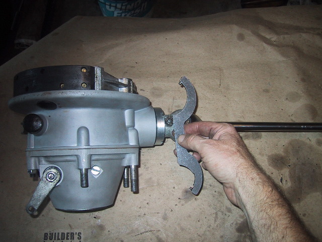 Use the URAL pin spanner to tighten the drive shaft bearing nut... |
 Remember this nut has left hand threads! So left is tighten. |
 Snug plus a little more is good enough. For those who just have to know... 55 ft/lb. or 68.6 to 88.2 Nm. |
 Make sure the hog ring is in the middle of the 3 grooves, slide the two finger yoke on the splines and press the rubber coupler on the end. Grease the splines when installing on bike or during storage. |
 If you are the real anal type...when installing the FD on the bike; make sure you align the finger yoke and U-joint yoke so they are in "phase". This is more important on the sidecar driveshaft as the rubber coupler is not a U-joint. Remember to "Run-In" the final drive and follow the Run-In service for the first 1500 to 2500 km's with new gears. |
|
|