|
|
2wd Sidecar Driveshaft Repair
|
|
2wd Sidecar Driveshaft Repair
A. 2wd Sidecar Driveshaft Removal
Tools Needed: Jack, wire cutters, screw driver, 12mm wrench, needle nose pliers, Ural "Y" combo pin/nut tool, hammer and block of wood.
Time required: 45 minutes or less.
 Use a jack to the inside of the frame to lift the hack wheel up as high as practical. You can also tip the rig over onto its left side allowing it to rest on the crash bar. |
 Use a pair of wire cutters to remove the safety wire around the 2 bolts... |
 ...that secure the driveshaft fork assembly to the final drive. |
 Use a 12 mm wrench to remove the 2 bolts once the safety wire is removed. |
 Place the bolts in a container so they will not get lost. |
 Use an appropriate type screw driver to loosen the hose clamp securing the rubber gaiter to the sidecar driveshaft. |
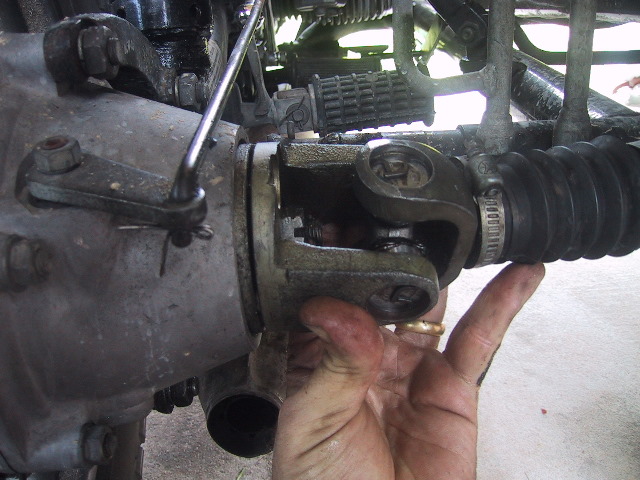
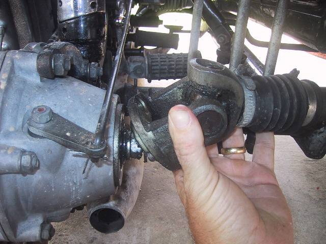 Remove the driveshaft fork assembly by sliding it into the driveshaft... |
 ...turn the output fork back to the rear.... |
 ...lift the driveshaft up and pull the driveshaft fork assembly... |
 ...free of the driveshaft. Set the assembly aside were it will not get dirty or damaged. |
 Now remove the sidecar wheel, use a screw driver... |
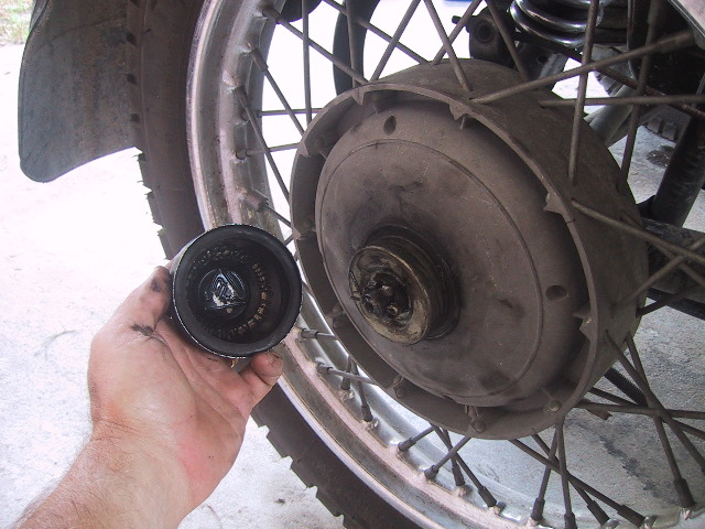 to remove the hub cap it equipped. |
 Use a pair of pliers or your fingers to bent and remove... |
 ...the cotter pin. |
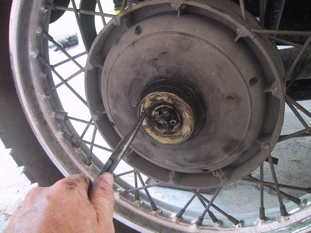
 Use the Ural "Y" combo pin and nut wrench to remove... |
 ...the castellated nut and dust cover. |
 So you don't lose the parts, place them in the inverted hub cap and place the cap somewhere where it will not get knocked over. |
 Remove the wheel from the axle and roll it out of the way. |
 Mark the metal part of the brake shoes with an "A" and "B" so they can be returned to their original positions and then... |
 ...grasping each side and pulling outward, remove the shoes and springs as a unit. Set the shoes off to the side where they will not be in the way. |
 Use a 12mm wrench to remove the brass adjustment nut from the brake actuator rod... |
 ...Slide the brake actuator arm aft to free the rod, place the barrel and adjustment nut back on the rod to prevent loss. |
 Use the 12mm wrench to remove the 3 bolts holding the brake back plate to the wheel lever. |
 Place the bolts and washers into your small parts bin to prevent loss. |
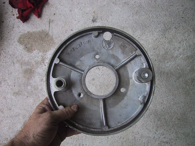
 Pull the back plate... |
 ...free of the wheel lever. |
 You can now see the sidecar short axle passing through the splined bushing and large washer. |
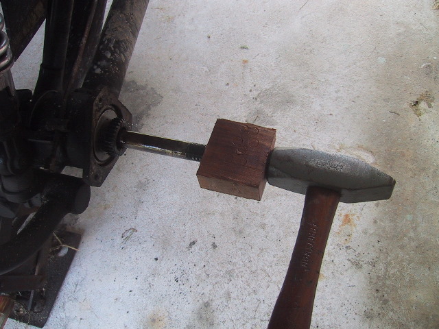 Use a block of wood and hammer to drive the short axle and driveshaft through the bearings in the wheel lever. |
 Once the driveshaft is free of the wheel lever (you can see the 6207 bearing is now free to the rear of the wheel lever)... |
 ...grasp the far end of the driveshaft... |
 ...and pull the driveshaft assembly free. Usually, the 6207 bearing and dust cover comes off on the short axle. Watch for the large flared spacer bushing on the short axle (in front of 6206 bearing on short axle) as it is free to fall off. Place the driveshaft assembly aside. |
 A straight on view of the wheel lever with the splined bushing and 6207 bearing in place. |
 Take your finger or use a pick and swipe the inside of the splined bushing to remove... |
 ...the ring spacer for the sidecar wheel. This sometimes is stuck to the back of the wheel when removed. Use care not to lose or misplace it. Put it in the parts bin so it does not get lost. |
If the ring spacer is grooved and worn like the one on the left, replace it with a new one as shown on the right. If you don't, there will slop in the sidecar wheel when mounted and the cotter pin may not go through the castellated axle retaining nut. |
 A view from underneath the sidecar looking through the back side of the wheel lever and splined hole of the splined bushing.
|
 From underneath the sidecar, use a tommy bar and hammer to tap the splined bushing even with the inner race of the 6206 bearing and then proceed to tap around the back of the inner bearing race...
|
 ...to knock the bearing and splined bushing free.
|
 The wheel lever is now empty.
|
 Clean the disassembled parts in your solvent of choice and inspect for wear. Replace bearings and worn parts as needed.
|
 Here is an example of wear on the splined short axle. You can see the the splines next to the axle are worn down with a visible ridge. This should be replaced but can still be used if necessary.
|
B. Repair of Sidecar Driveshaft
Tools Needed: Vise, tommy bar, hammer, block of wood, pick or small screw driver, needle nose pliers, 5/8's or 15mm socket, bearing separator kit and grease gun with needle tip.
Time Required: 1.5 hours or less.
 To remove the 6207 bearing from the splined bushing, open the jaws of a vise enough to rest the outer race of the bearing on the jaws... |
 ...use a tommy bar and hammer to tap around the inner face of the splined bushing until it drops through the bearing. Have something soft for the splined bushing to land on so it does not damage the splines. |
 Here are the 3 pieces separated; the 6207 bearing, washer and splined bushing. Check bearing for serviceability and replace if needed. |
 Examine the front and... |
 ..back of the washer for grooving or heavy wear. This washer is reuseable. |
 Examine the splined bushing out teeth (these mate to the splines of the wheel hub) for excessive wear. The teeth should be square and smooth... |
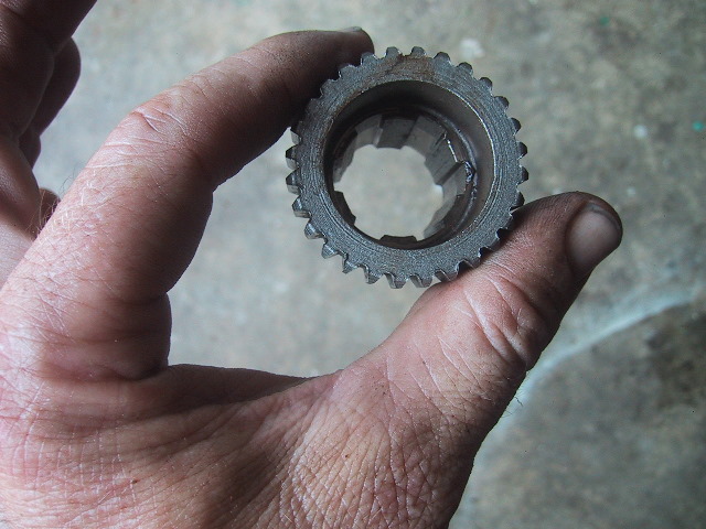 examine the inner splines (these lock with the splines on the short axle) for wear and galling. This is a good bushing. |
 To install a new 6207 bearing, set the bearing on a hard surface, place the washer on next and then carefully start the splined bushing into the bearing taking great care not to cock the bushing in the bearing. Then use a block of wood to drive the bushing through the bearing... |
 ...then set the bearing on the open jaws of a vise so the outer edge of the inner race is just supported... |
 ...then finish driving the splined bushing fully through the bearing using the block of wood and hammer. |
 The splined bushing and 6207 bearing are now ready to be installed. |
 The drive shaft fork assembly has an 38 X 3 mm O-ring that should be replaced when the assembly is removed. |
 Use a pick or thin screw driver to remove the old O-ring... |
 Use some silicone grease on the new O-ring and slide it into the groove. |
 Examine the splines of the driveshaft fork for wear. The splines should be square, even and sharp, having no excessive wear. This splined shaft is good. |
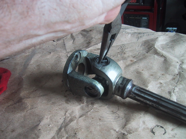
 To replace the U-joint or disassemble a non zerk equipped joint for servicing, use a pair of needle nose pliers to squeeze and remove the retaining clips... |
 ...of two opposing cross cups. |
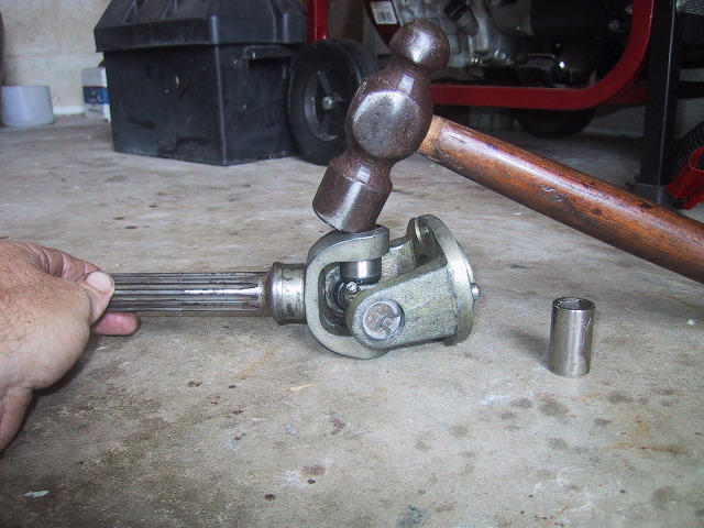
 Use a 15mm socket and hammer to drive the cross through the yoke... If a grease zerk is installed, position the zerk so that it is being driven toward the center of the cross and not toward the yoke. Zerk is just visible above lower yoke. |
 ...grease zerk is here, if you attempt to drive the cross through the other way...the zerk will be forced against the yoke above and jam/break... |
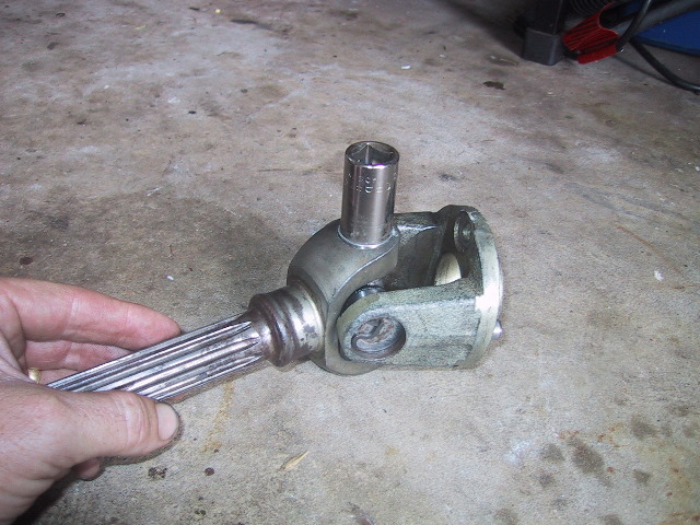
 ...tap the cross through just enough to drive the opposing cup out enough... |
 ...so that you can grip it in the jaws of a vise. |
 Work it back and forth with a slight pull up to remove the cup... |
 ...then turn the fork down and press the cross arm through where the cup was removed... |
 ...enough to clear the opposing cup and separate the two yokes. |
 Now do the same with the last half of the cross. Remove the 2 remaining retaining clips... |
 ...you can start the cross through by setting it on a hard surface and using the socket and hammer. Then just pick it up in your hand like before and tap the cup out enough to grab with the vise. |
 Driveshaft fork assembly fully dismantled. If you do not have U-joints with zerks, you can now clean and repack the needle bearings for reassembly.
|
 If you are replacing the U-joint, I recommend using a Precision #341 as it is fitted with a grease zerk and will provide a longer service life if maintained. |
 Here is what you get for $30. |
 The long zerk fitting that comes with the U-joint will not work. The long zerk hits the inside of the yoke and will break. You must get a short zerk and install it. |
 Put the old U-joint in the box and save them as you can possibly use the old parts if the new joint gets damaged during assembly or while in service. |
 When assembling the joint, you want to think about zerk placement. You want the zerk in such a position that you can get to it for greasing. If the zerk were to go in the opposite of above, it would be difficult if not impossible to get a grease fitting on it. |
 Use the needle nose pliers to install one of the retaining clips in the yoke. This will prevent you from driving the cross/cup too far through the yoke when installing. If this were to happen, it would damage the cups and seals. |
 Remove the cup next to the zerk... |
 ...insert the cross into the yoke hole without the retainer clip and push it up enough to get the opposing cross with cup over the yoke hole with the retaining clip in place. |
 Press the removed cup into the yoke hole with finger pressure. Make sure it is square to the hole and not cocked... |
 Turn the yoke over so the retaining clip side is facing up. Place the yoke on a hard surface and while keeping the bottom cup flat on the surface, tap the top of the yoke to drive the bottom cup into the yoke. |
 The bottom cup is now flush to the yoke hole... |
 ...the other cup is now almost seated against the retaining clip, turn it back over to the flush side... |
 ...and take a 15mm socket and the hammer... |
 and finish driving the cross through until... |
 ...the opposing cup seats against the retaining clip. |
 Before going any further, check for smooth movement of the cross. If it binds or is very difficult to move, something is wrong. Take it apart and check that one or more of the needle bearings did not get pushed to the bottom of a cup or that one of the seals got buggered. This is where the old parts may come in handy. |
 If the joint articulated smoothly, pop the retaining clip in. |
 Now we can install the splined shaft yoke. |
 Install one retaining clip into the splined shaft yoke... |
 Remove a cup of the cross, insert the cross into the yoke hole without the retaining clip... |
 ...push the cross up into the hole until you can angle the opposing cross with cup over the hole in the splined yoke with the retaining clip in place. |
 Check that the cross is centered in the hole... |
 ...and then press the last cup into place using finger pressure only, maybe a light tap with the hammer. |
 Place the driveshaft fork assembly on a hard surface with the exposed cup facing down. Using a hammer, tap the top of the yoke until the cup is flush with the yoke against the floor/surface. |
 A view showing the zerk and the upper cup almost seated against the retaining clip... |
 ...flip the assembly over so you are looking a the flush cup.... |
 ...place the 15mm socket on top and ... |
 ...tap the cup through until the opposing cup seats against the retaining clip. Check for smooth movement of the joint is all directions. If there is a problem, disassemble the affected side and inspect. |
 If all is well, put the last retaining clip into place. |
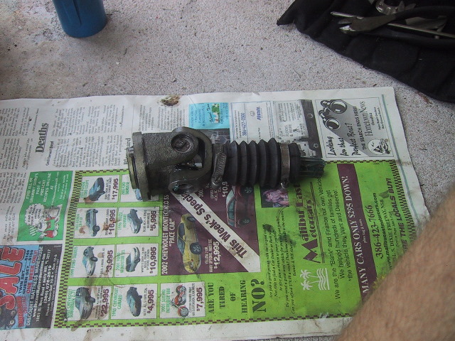
 The driveshaft fork assembly is now ready to install. Note the position of the zerk. It will be easy to access after installation. New U-joints must be greased after installation and before driving the motorcycle!!!! |
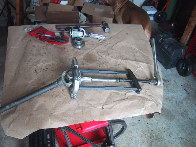 The easiest way to remove the 6206 bearing from the sidecar short axle is to remove the U-joint, set the axle upright on the open jaws of a vise and hammer the axle through the bearing and dust cover. However, this U-joint was in good shape and did not need replacement. So a bearing separator was used to pull the bearing free. |
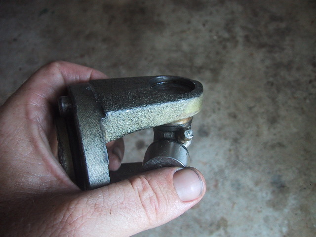
 This is the same Pittsburgh #93980 bearing separator kit as used in Chapter 7.8, Pinion Gear Disassembly, and can be purchased at Harbor Freight. This is a view from the driveshaft end...
|
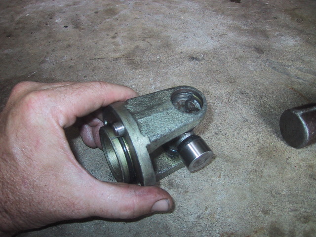
 ...and one from the short axle end after the 6206 bearing and dust cover were pulled free. It took 10 minutes to set up and 30 seconds to pull. Again, if replacing this U-joint, it is simple to use the vise as explained above to drive the axle through the bearing. It almost takes the same amount of time. |
 Bearing and dust cover removed. If the short axle is worn or galled, it must be replaced. |
 To install the new 6206 bearing, clamp the short axle yoke in a vise, slip the dust cover and bearing on... Note: If you removed the U-joint, this would be how you would remove the bearing by setting the bearing on the open vise jaws and tapping the axel through the bearing. |
 ...use a block of wood and a hammer to seat the bearing. I toss an old flywheel lock washer over the top of the bearing just to protect the bearing seal...always save those old worn out parts...they come in handy. |
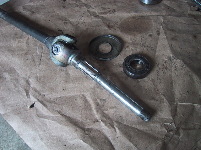
 Short axle and driveshaft ready to be installed. |
 Here is the driveshaft laid out with the driveshaft fork assembly inserted into the driveshaft (right side). Make sure when you assemble the driveshaft on the motorcycle that the yokes are "in phase" or in alignment with each other. Note how the inside left yoke and the yoke of the fork assembly on the right are "mirror image" or matched to each other. |
 The yokes must be in-line with each other or as the driveshaft turns it will be unbalanced and bend the driveshaft and place undue wear and tear on the U-joints and bearings. Looking down across the top of the two U-joints there is about 1/4" of twist. This is caused from "flying chair" and abuse which twists the soft metal of the shaft. Bends and twists like this can be hammered/twisted out. In severe cases a new shaft can be welded to the yokes or the unit can be replaced. |
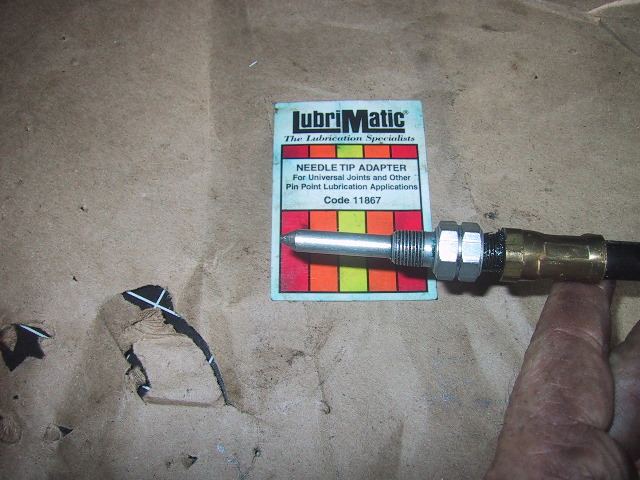 While the driveshaft is out, it is much easier to grease the U-joints. I use a Lubrimatic Needle Tip Adapter #11867 which is available at Sears and most automotive stores. |
C. Installing Repaired Sidecar Driveshaft
Tools Needed: Same as for Removal plus safety wire and grease.
Time Required: 1 hour
 Before installing the wheel lever components, thoroughly clean out the cavity with cleaning solvent and let dry. |
 Using finger pressure or light taps with a hammer, place the 6207 bearing and splined bushing combo into the wheel lever... |
 Use a block of wood to protect the splines and drive the bearing in with a hammer. Use care to not get the bearing cocked while driving it in. |
 When seated, the bearing will be slightly recessed into the wheel lever housing... |
 ...grease both the internal and external splines. |
 Grease the driveshaft fork assembly splines and give the distance bushing a light coat. Make sure the "flare" of the bushing is to the outside. Small end goes toward the small bearing is another way to remember. |
 Slide the bushing against the bearing. Hint: a glob of grease or two on the bearing face will hold the bushing in place whilst installing. |
 From behind the sidecar, insert the short axle end of the driveshaft in front of the sidecar rear suspension and through the driveshaft tunnel and into the wheel lever housing through the splined bushing... |
 ...grasp the short axle and pull it through with a twisting motion to engage and seat the splines. |
 Get a long block of wood and hammer, set the beside the sidecar axle... |
 ...use them to beat against the knuckles of the short axle yoke from underneath the sidecar to seat the 6206 bearing into the back of the wheel lever housing... |
 ...this is the view from underneath, try and get the bearing flush with the lever housing. Turn the driveshaft so the short axle knuckle is at 9 o'clock, place the wood block on the yoke knuckle here... |
 ...like so, and then give a sharp blow with a hammer... |
 ...then turn the driveshaft 180 degrees to the opposite yoke knuckle is now a 9 o'clock. Place the wood on the knuckle and strike with hammer. Repeat turning of driveshaft and strikes until 6206 bearing is seated. Use care not to cock bearing into wheel lever housing. |
 The bearing is seated when the dust cover is flush to the back of the wheel lever housing. |
 Check to make sure the 6207 bearing and splined bushing were not driven out during the installation of the driveshaft. |
 Grease the inner splines of the driveshaft... |
 ...and the splined shaft of the driveshaft fork assembly. |
 Install the rubber gaiter and tighten the inside hose clamp. |
 Raise the driveshaft up into the driveshaft tunnel and insert the driveshaft fork assembly into the end of the driveshaft. Taking care to align the yokes of the driveshaft as shown above. |
 Lower the driveshaft and slip it over the end of the rear wheel axle and turn the fork assembly so the 2 pins on the assembly... |
 ...can engage their respective holes on the final drive. |
 Use a 12mm wrench to install the 2 retaining bolts and washers holding the driveshaft fork assembly to the final drive. |
Slip the rubber gaiter into the groove on the driveshaft and tighten the hose clamp. |
 Clean the brake back plate with your solvent of choice... |
 This is a good time to grease the brake lever cam pin. Mark the alignment of the cam and lever. Mark it in some manner that will not come off. This is important as if the alignment moves it will affect your brakes one direction or the other (i.e. too tight or too loose) |
 Use a 13mm wrench to remove the nut and washer holding the brake cam lever to the backing plate. Strike the exposed end of the cam pin with a hammer to drive it back through the brake plate. |
 Clean the parts in your solvent of choice and dry. Then grease the cam pin... |
 ...insert it back through the brake plate... |
 ...place the brake lever arm on the cam pin carefully aligning your marks, then use the 13mm wrench to tighten the washer and nut. |
 Install the short axle distance washer... |
 Use a 12mm wrench to install the 3 bolts holding the brake back plate to the wheel lever housing... |
 ...grease the brake rod barrel and install the rod, barrel and brass adjustment nut. Leave the adjustment loose. Grease the 2 brake shoe cams. |
 Install the brake shoes. |
 Install the wheel... |
 ...place the dust cover on... |
 ...tighten the castellated nut using the Ural "y" combo tool... |
 ...install and bend the cotter pin... |
 ...if used, install the hub cap. Adjust the sidecar brake. |
 Lower bike and remove jack or turn motorcycle back off left side. |
 Recheck tightness of driveshaft fork assembly bolts... |
 ...and safety wire these 2 bolts. Make sure the safety wire goes around the outside of the yoke like shown above. If you put the safety wire to the inside of the U-joint the wire will spin and cut into the castellated nut securing the rear wheel axle. |
Go ride and make final sidecar brake adjustment. |
|
|